Tools and commands (View)
The toolbar includes the following buttons:
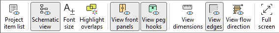
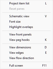
They are also available in Main Menu > View:
Project item list (View)
Toggles displaying the list of products and accessories in your current planogram. Consult the description of this pane in the dedicated section: Project item list.
- Keyboard shortcut: L
- Supported values:
- Pressed (checkmarked): Project item list is displayed on screen.
- Not pressed (not checkmarked): Project item list is not displayed.
- Default value:
- In the task named Publish: Pressed (checkmarked)
- In other tasks: Not pressed (not checkmarked)
Note: The list can also be closed by clicking on the cross icon in its upper right corner.
Reset panes
This command resizes and repositions all the user interface panes to their default values.
Schematic view (View)
Toggles a special display mode showing all the products in your project as a simplified, schematic view.
- Keyboard shortcut: V
- Supported values:
- Pressed (checkmarked): Schematic view is enabled.
- Not pressed (not checkmarked): Schematic view is disabled.
- Default value: Not pressed (not checkmarked)
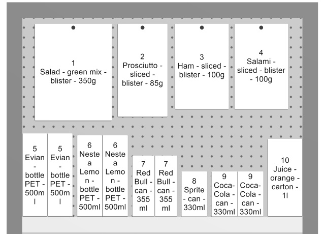
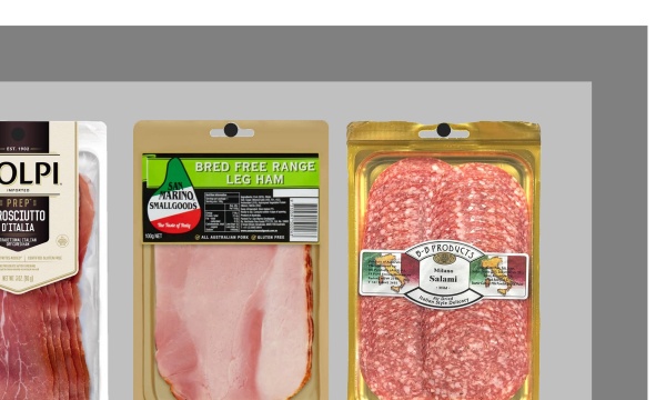
Example of Schematic view
Important note: There are several options to configure Schematic view. Consult Schematic view (Settings) and to Schematic view / Generic products / Dimensions for instructions and examples of these options.
Font size
With this tool, you can adjust the size of product labels with your mouse.
Instructions:
- Activate the tool from the menu.
- Place your mouse cursor in the visualization area.
- Press and hold the left mouse button.
- Move your mouse left, right, up or down. The text size changes.
- Release the mouse button.
- Activate another tool to exit this feature. E.g., Zoom
To set the text size back to its default value:
- Activate the tool from the menu.
- Place your mouse cursor with the visualization area.
- Click the left mouse button.
- Activate another tool to exit this feature. E.g., Zoom
Tip: You can also set the font size value precisely with the setting named Font height. That section also explains in detail which label texts are affected by this tool.
Highlight overlaps
Toggles highlighting the products which physically overlap other items or bay components.
It is especially useful to identify overlaps in your project if you have disabled Collisions (Settings), because in this case items can easily be mistakenly placed partially over other items.
- Supported values:
- Pressed (checkmarked): items that overlap are highlighted in yellow.
- Not pressed (not checkmarked): items that overlap are not highlighted.
- Default value: Not pressed (not checkmarked)
Example of Highlight overlaps
View front panels
Toggles the visibility of bay components of type: Front panel. Hiding front panels allows selecting and editing products behind the panels, for example in case you have glass doors on a cooler. You can then display the front panels once all items behind are positioned.
- Supported values:
- Pressed (checkmarked): front panels are visible.
- Not pressed (not checkmarked): front panels are hidden.
- Default value: Pressed (checkmarked)
Note: Consult Front panel (New bay components) for details on such bay components.
View peg hooks
Toggles displaying the actual hooks of pegged products. Showing the hooks can help visualizing where the peg is located exactly, including any offset.
- Keyboard shortcut: K
- Supported values:
- Pressed (checkmarked): front panels are visible.
- Not pressed (not checkmarked): front panels are hidden.
- Default value: Pressed (checkmarked)
Example of View peg hooks
View dimensions
Toggles the display of dimension lines and values for the objects in your planogram.
Showing dimensions assists you when placing products, building or resizing shelving and room elements.
- Keyboard shortcut: D
- Supported values:
- Pressed (checkmarked): dimensions are displayed.
- Not pressed (not checkmarked): dimensions are not displayed.
- Default value: Not pressed (not checkmarked)
Note: You can configure various options for display of dimensions in Settings. Consult the sections under Schematic view / Generic products / Dimensions.
Depending on the context, various dimensions are displayed on screen:
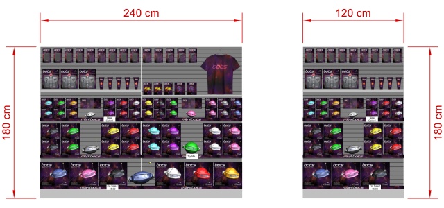
By default, the overall width and height are shown for each isolated bay and each group of adjacent bays:
Additionally, for each bay with at least one selected shelf, vertical shelf measures are shown. And for each bay with at least one Dividing panel selected, lateral distances between each Dividing panel are displayed, as shown below:
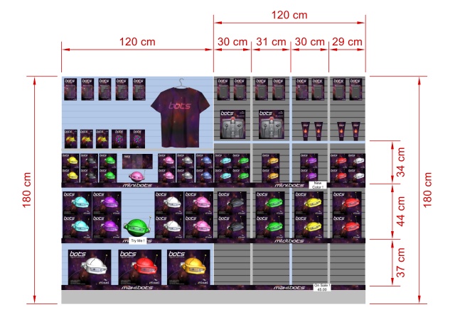
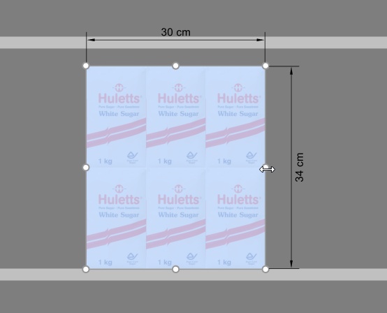
The dimensions of any bay, bay component or block of products are also displayed when clicking on one of its round handles in the corresponding editing mode, as shown below:
Note: a dimension is only displayed if the viewing angle and the available space allows. If you can’t see a desired dimension, use Zoom, Pan tools to adjust the view accordingly.
View edges
Toggles the drawing of edge lines on objects. This is useful to help distinguish each product and bay component in your planograms.
- Keyboard shortcut: E
- Supported values:
- Pressed (checkmarked): edge lines are drawn.
- Not pressed (not checkmarked): edge lines are not drawn.
- Default value:
- Preview in Create bays: Pressed (checkmarked)
- Visualization area:
- PlanogramBuilder light version: Pressed (checkmarked)
When checkmarked, the edges are drawn for the following cases and objects:
- For all bay components (including in Create bays)
- For Generic products, consult Insert generic product.
- For all products, when Schematic view is checkmarked and Product style is set to Box & label.
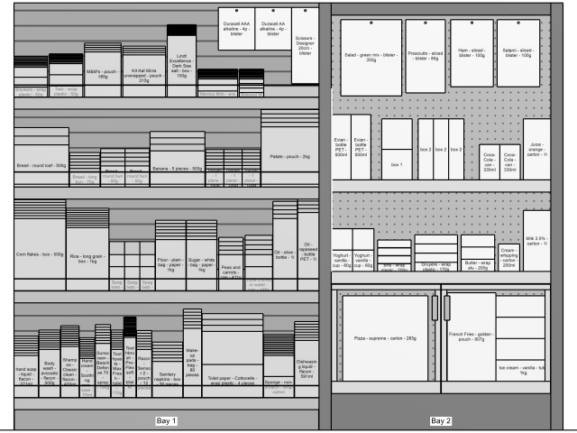
Above example:
- View edges: checkmarked
- Schematic view: checkmarked
- Product style: Box & label

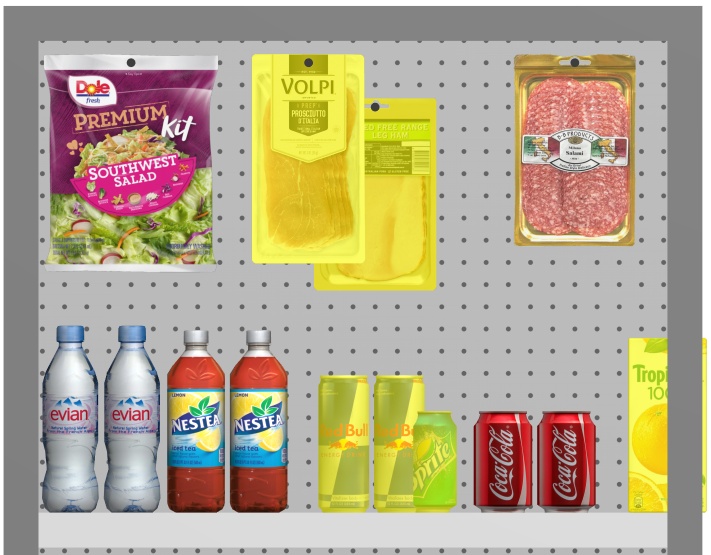
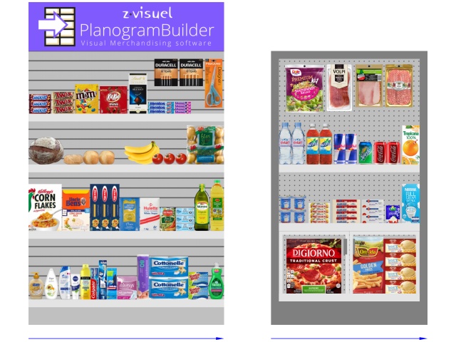
Above example:
- View edges: checkmarked
- Schematic view: not checkmarked
View flow direction
Toggles the display of arrows indicating Flow direction at the base of each bay in your project. This command has no effect on bays for which Flow direction hasn't been defined. Consult Flow direction for details on how to set the flow direction for your bays.
- Supported values:
- Pressed (checkmarked): front panels are visible.
- Not pressed (not checkmarked): front panels are hidden.
- Default value: Not pressed (not checkmarked)
Full screen
This command toggles the full screen mode.
- Keyboard shortcut: F11: toggles Full screen
In this mode, the planogram visualization is maximized to fill the whole screen.
You can still use commands for Edit, View and Navigation from the toolbars and from the main context menu.
You can also still use Mouse & keyboard shortcuts to perform any supported actions.