Selected bays
This section lets you view and edit the properties of the selected bays.

Parameters of the whole bay (Selected bays)
These are parameters for the entire selected bay.
Overall width (Selected bays)
The physical width of the selected bays in the current measurement unit.
- Supported values: positive numeric value [0-9 and decimal point]
- Default value: selected bay width
- Example: 240
Changing this value resizes the whole bays in width. Note that the thickness of components is maintained, thereby letting you effectively create width variations of same bay.
Note: If multiple selected bays have different widths, no value is displayed, but you can still assign a common value by typing it in the textbox.
Tips:
- You don't need to type the actual measurement unit (e.g., cm ), only the value.
- The overall width can also be defined with the mouse. cf. Resize (Edit bays).
- Change the way components are resized with Resizable with bay (Selected bay components).
- View dimensions onscreen is helpful when resizing shelving and components.
Overall height (Selected bays)
The physical height of the selected bays in the current measurement unit.
- Supported values: positive numeric value [0-9 and decimal point]
- Default value: selected bay height
- Example: 185
Changing this value resizes the whole bays in height. Note that the thickness of components is maintained, thereby letting you effectively create height variations of same bays.
Note: If multiple selected bays have different heights, no value is displayed, but you can still assign a common value by typing it in the textbox.
Tips:
- You don't need to type the actual measurement unit (e.g., cm ), only the value.
- The overall height can also be defined with the mouse. cf. Resize (Edit bays).
- Change the way components are resized with Resizable with bay (Selected bay components).
- View dimensions onscreen is helpful when resizing shelving and components.
Position Y (Selected bays)
The position of the selected bays on the Y axis in the current measurement unit.
- Supported values: positive/negative numeric value [+-0-9 and decimal point]
- Default values: no default value (the initial position depends on where the component was dragged)
- Example: 0
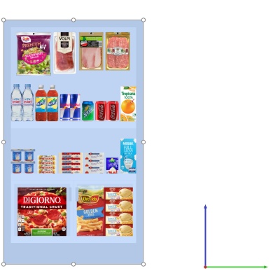
Example of a bay position (placed at 0, 0)
Note: The position is calculated from the lower back edge of the bay at the mid-point of its width.
Advice: The position can also be defined with the mouse. cf. Move (Edit bays).
Position Z (Selected bays)
The position of the selected bays on the Y axis in the current measurement unit.
- Supported values: positive/negative numeric value [+-0-9 and decimal point]
- Default values: no default value (the initial position depends on where the component was dragged)
- Example: 420
Example of a bay position (placed at 0, 0)
Note: The position is calculated from the lower back edge of the bay at the mid-point of its width.
Advice: The position can also be defined with the mouse. cf. Move (Edit bays).
Flow direction
Indicates which way people are most likely to travel in the aisle where the selected bays are located.
- Supported values:
- (undefined): no specific direction.
- to right: people walk from left to right of the bay seen from the front.
- to left: people walk from right to left of the bay seen from the front.
- Default value: (undefined)
- Example: to right
Note: cf. View flow direction to learn how to indicate direction follow with arrows on the screen.
Bay name
Descriptive name of the selected bay.
The name can then be displayed on the bay (Show bay labels or View as boxes), as well as in Project item list and in Reports. This is useful to identify each shelving unit in your planograms.
- Supported values: text, including Unicode characters for non-Latin text values
- Default value: empty (= no name)
- Example: my drink cooler
Front image
An image displayed on the front face of the bay for a more realistic look.
- Supported value: image file accessible from your computer
- Default value: empty (= no image)
- Example: my_brand_gondola.jpg
Supported image file formats and requirements
cf. Supported image file formats and requirements.
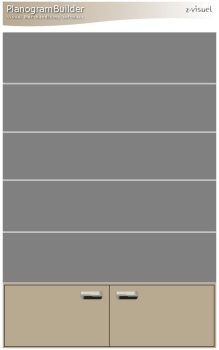
Example with an image applied to the base and the top panel of a bay
Instructions:
- Click on Browse.
- Select the desired image file on your PC.
- Click on Open.
- Wait for the image to upload.
To remove the background image, click on the small red cross button.
Notes:
- The image is only be displayed on bay components that have Display the bay front image checkmarked.
- The image is automatically stretched to fit the overall dimensions of the components that have Display the bay front image checkmarked.
Locked bay components
Toggles the possibility to modify the selected bays.
This is useful to prevent accidental modification of shelving.
- Supported values:
- Checkmarked:
- The bay and its components can still be selected, but their properties cannot be changed any more, except the parameters Locked bay components and Locked accessories.
- Existing components cannot be moved with the mouse.
- Existing components cannot be deleted from the bay.
- New components cannot be added to the bay.
- Not checkmarked: The bay and its components can be modified.
- Default value: Not checkmarked
Note: The chosen value is saved with the project for each bay.
Locked accessories
Toggles locking the accessories on the selected bays.
This is useful to prevent accidental changes of the accessories placed on the bay. Let’s suppose you have created a bay with several accessories such as: bay header, panel and Shelf strip. Locking accessories will allow you to add and move products on the shelves without risking displacing the accessories at the same time.
- Supported values:
- Checkmarked: Accessories can't be moved, deleted or added on the bay.
- Not checkmarked: Accessories can be moved, deleted and added on the bay.
- Default value: Not checkmarked
Note: The chosen value is saved with the project for each bay.